Dyketector range

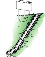
A system of jointed channels designed to receive the flow from a drainage pipe and discharge it directly into the water course thus preventing any erosion of the embankment. Ideal for the deeper dykes of the fenland area and any situation where the outfall pipe is discharging at a distance above the water course. The geo-textile attached to the side flanges forms a permanent anchor for the units. Cover with top soil and allow vegetation to grow through.

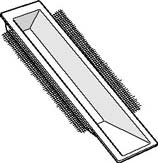
Double ended Dyketector headwallPipe sizes: Up to 150mm |
 |

Single ended Dyketector headwall Table Ref: F
Pipe size: 150mm plastic, 1000mm lengths.
Approximate weight: 15kg.
to be used with dyketector splash plates where the outfall pipe is more than 700mm from ditch bottom (see table).
Dyketector channel Table Ref: E 1000mm D 600mm
1000mm and 600mm lengths
Approximate weight: 15kg. and 10kg. respectively
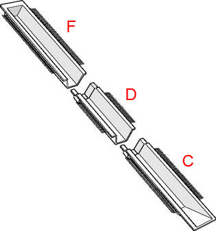
The spigot and socket ends enable these units to be easily connected to the dyketector splash plate and headwall units to ensure maximum protection to the embankment irrespective of distance of the drain from water course.
Dyketector splash plate Table Ref: C 1000mm B 600mm
1000mm and 600mm lengths
Approximate weight 15kg. and 10kg. respectively.
To be used with the single ended dyketector or with the dyketector channels (see table) to minimize erosion at the ditch bottom.
| Example of Angle | Max. vertical invert level for 150 diameter pipe | ||||
|---|---|---|---|---|---|
| 30 | 200 | 550 | 700 | 1000 | 1200 |
| 45 | 500 | 900 | 1200 | 1500 | 1900 |
| 60 | 700 | 1100 | 1500 | 2000 | 2400 |
| Components Required | A | B+F | C+F | C+D+F | C+E+F |
A=Double ended 1m dyketector, B=600mm long dyketector splash plate, C=1000mm long dyketector splash plate, D=600mm long dyketector channel extension E=1000mm long dyketector channel extension, F=Single ended dyketector headwall
INSTALLATION
Open out a trench below the outfall to the outside dimensions of the unit and sufficiently deep for the side flanges to be just below the surface. The splash plate where possible should be on firm ground at the ditch bottom. Select units which are long enough to reach above the outfall pipe, mark the position of the pipe and using a hammer and punch or masonry disc cutter, carefully pierce the unit and enlarge the hole to the required diameter. Position outfall pipe so that it just protrudes into channel, carefully press units into position and either pin the geo-textile down or cover with soil.


